
Ideally, the membrane pores are filled with gas and reject liquid permeation to ensure low mass transfer resistance. The overall mass transfer process involves three resistances in series: the gas phase resistance, the membrane resistance, and the liquid resistance. In the membrane absorption process using hydrophobic membranes, the gas to be absorbed first transfers from the bulk gas phase to the gas-membrane boundary and then diffuses through the membrane pores to the gas–liquid interface where the absorption occurs 19. Membrane contactors, which are made up of several hollow fibers assembled, have a large specific surface area, providing a high interface area for gas–liquid contact 15, 16, 17, 18. Hydrophobic polymer materials such as polypropylene, polytetrafluoroethylene, and polyvinylidene fluoride are the most common hydrophobic membranes used in CO 2 absorption processes 14. Overall, the use of MCs represents a promising approach for gas–liquid mass transfer in various industries, and further research is needed to optimize their performance and commercial viability 10, 11, 12, 13. MCs have been explored to replace traditional packed columns in carbon capture and sulfur dioxide removal applications 9. MCs offer a substantial interfacial area, promoting the efficient mass transfer and enabling the effective removal of specific impurities like CO 2 and H 2S from gas streams.įurthermore, MCs demonstrate low-pressure drops, decreasing energy consumption and operating costs 7, 8. This unique structure enables several advantages regarding mass transfer rates and process efficiency 6. They consist of a porous membrane that acts as a physical barrier between the gas and liquid phases, allowing selective transfer of gases while preventing the mixing of the two phases. The review highlights working principles, comparisons with gas separation, module designs, and commercial implementations 3, 4, 5. Challenges include pore wetting, solvent selection, and fouling with potential solutions.

Membrane contactors (MCs) gain attention in pilot and industrial scales, particularly for carbon capture 2, reducing energy consumption and cost.

These factors include the gas–liquid contact area, mass transfer coefficients, and pressure drop 1. The mass transfer and hydrodynamic performance of separation devices used in gas absorption processes are influenced by several crucial factors. These findings highlight the significant promise of FFMC for applications in CO 2 capture.
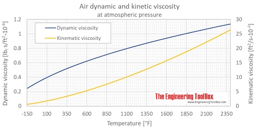
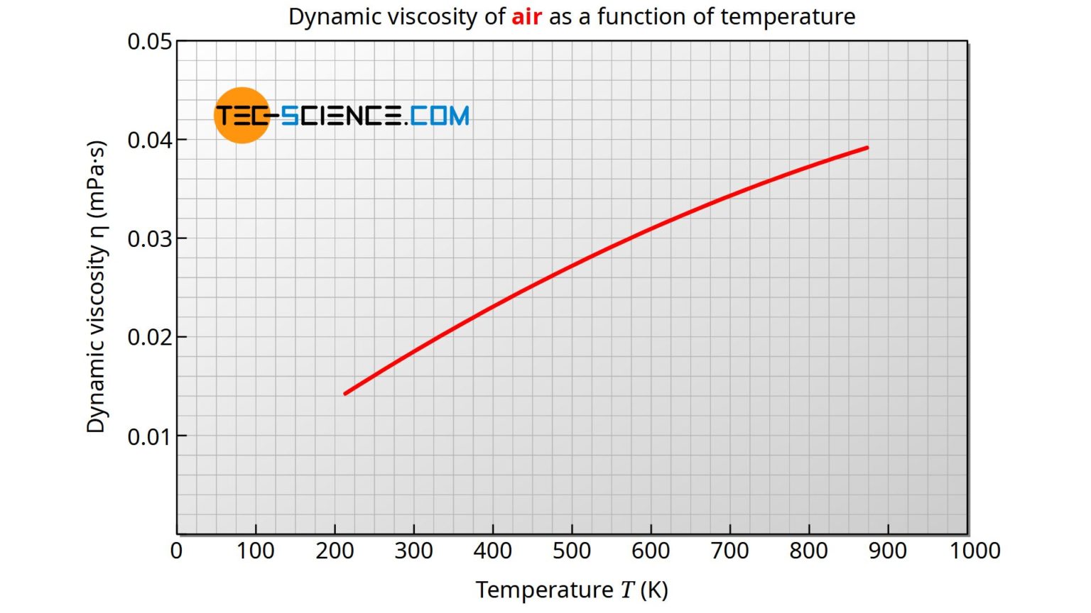
#DYNAMIC VISCOSITY FORMULA FOR AIR SOFTWARE#
We employ COMSOL Multiphysics 6.1 simulation software and finite element analysis to validate our findings, demonstrating a close agreement between predicted and experimental values, with an average relative error of approximately 4.3%. Our results reveal a clear advantage of FFMC, achieving an impressive 85% CO 2 removal efficiency compared to 60% with wet membranes. By analyzing factors such as membrane surface area, gas flow rate, liquid inlet flow rates, gas–liquid contact time, and solvent loading, we examine the CO 2 absorption process in both contactors. This study investigates the efficacy of wet and falling film membrane contactors (FFMC) in enhancing CO 2 absorption in a monoethanolamine (MEA) aqueous solution. A hollow fiber membrane contactor is an emerging technology that combines the advantages of separation processes and chemical absorptions. Therefore, it is necessary to implement appropriate actions to moderate CO 2 emissions. The release of excessive carbon dioxide (CO 2) into the atmosphere poses potential threats to the well-being of various species on Earth as it contributes to global working.


 0 kommentar(er)
